


That sharp front-end clunk on the 1st-generation Honda Fit (2003 to 2008) that sounds like a "samba school" on cobblestone streets — even after you have already replaced shocks, bump stops, and sway bar links — almost always has one classic culprit: the play in the internal steering rack bushing (passenger side) combined with wear in the inner tie rods.
In this definitive technical guide based on a real 1h14min procedure in Paulo's garage following the Honda service manual, we gathered the complete no-shortcuts walkthrough: the masking-tape safety checklist, marking the U-joint with absolute care for the airbag Clock Spring, lowering the subframe, real caliper measurements of the bushing, replacing the Viemar inner tie rods, and all official torques in kgf·m / N·m right through the final tightening with the car on the ground.
Critical Safety & Engineering Warnings (Honda Fit EPS Steering Rack)
- 1. NEVER turn the steering wheel with the U-joint disconnected (risk of snapping the Clock Spring): Inside the steering wheel sits the spiral cable (clock spring) for the airbag and horn, which has a limited number of turns. With the column disconnected from the rack, lock the steering wheel centered and do not let it spin freely.
- 2. Keep a physical masking-tape checklist on the windshield: On a job with dozens of critical fasteners (wheels, subframe at 9,5 kgf·m, ball joints, tie rod ends, sway bar links, U-joint, EPS connectors), cross off each item only after verifying final torque — this prevents driving off with something loose or forgetting the electric power steering connectors.
- 3. Torque the subframe and control arms with the car's weight on the ground: Snug the bolts while raised and only apply the final torque of 9,0 to 9,5 kgf·m with the wheels resting on blocks/floor, avoiding twisting the rubber bushings.
- 4. Hold the rack bar when loosening the inner tie rods: Do not apply brute force to the inner tie rod without counter-holding the rack shaft (22 mm wrench), so you do not overload the pinion and the internal bearings of the electric steering motor.
Key procedure moments in the video
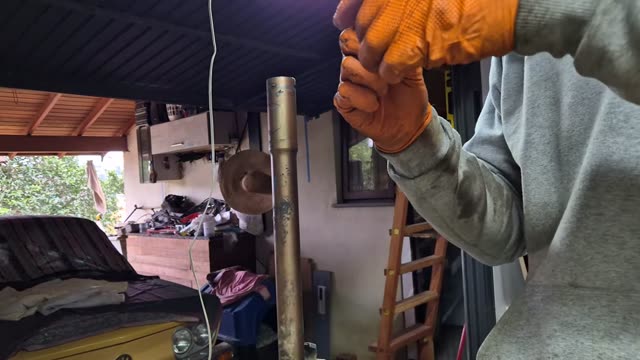 ▶ 00:20 Center jacking point, jack stands & checklist
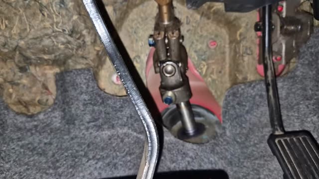 ▶ 06:20 Interior U-joint (10 mm) & Clock Spring alert
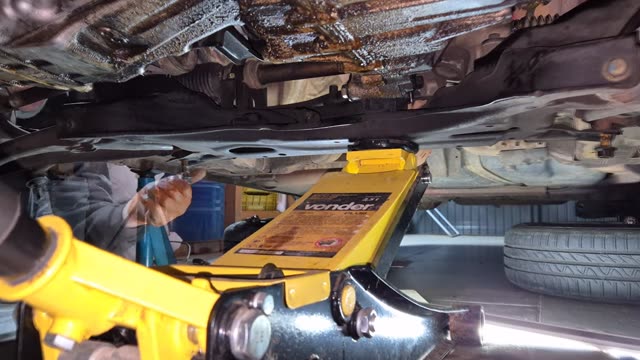 ▶ 19:40 Subframe lowering & EPS connectors
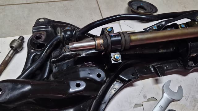 ▶ 35:00 Bushing swap in the vise & real measurements
 ▶ 59:10 Final torques (U-joint 2,8 / subframe 9,5 kgf·m)
Official Table of Confirmed Torques & Measurements (Honda Fit 2003–2008)
Scroll horizontally to see all table columns.
| Fastener / Component | Wrench / Size | Confirmed Torque | Practical Workshop Note |
|---|---|---|---|
| Subframe-to-body mounting bolts | 17 mm / 19 mm | 9,0 to 9,5 kgf·m (90 to 95 N·m) | The rear bolts are longer than the front ones; final torque with the vehicle's weight resting on the wheels |
| Inner tie rods to steering rack | 30/32 mm (tie rod) + 22 mm (rack bar) | 7,5 kgf·m (75 N·m) | Apply chemical threadlocker if you do not have a new OEM lock washer |
| Lower ball joint castle nut | Castle nut + cotter pin | 5,0 to 6,0 kgf·m (50 to 60 N·m) | Adjust within the range until the stud hole aligns to insert the cotter pin |
| Steering rack mounting to crossmember | 14 mm | 4,5 kgf·m (shorter side) / 5,0 kgf·m (longer side) | Unbolting on the bench lets you clamp the rack in a vise and extract the old bushing effortlessly |
| Outer tie rod end nut | 17/19 mm (and 14 mm on the shaft) | 4,4 kgf·m (44 N·m) | Count the turns when removing (in the video: 21,5 turns right / 19,5 left) for rough pre-alignment |
| Sway bar link nut at stabilizer bar | 17 mm + 5 mm Allen | 3,9 kgf·m (39 N·m) | Hold the center stud with a 5 mm Allen key so the nut does not spin freely |
| Steering column U-joint bolts | 10 mm (2 identical) | 2,8 kgf·m (28 N·m) | Mark with a punch/marker before loosening and do not turn the uncoupled steering wheel |
| Wheel lug nuts | 19 mm | 11 kgf·m (110 N·m) | Verified with a torque wrench after lowering the car to the ground |
Checklist of Tools, Parts & Supplies
Scroll horizontally to see all table columns.
| Item / Tool | Specification / Part Number | Role in Procedure |
|---|---|---|
| Inner Tie Rods (Right & Left) | Viemar 6802111 (Right) and 680313 (Left) | Replace worn joints with play (includes boot clamps and new nut) |
| Steering Rack Bushing | Reinforced Auto Flag (real dimensions: OD 29,74 mm · height 15 mm · ID 23,7 mm) | Eliminate the characteristic sharp clunk on the passenger side of the rack |
| Tie Rod Puller + Heat Gun | Jaw/screw-type puller | Pop the tie rod end without tearing the boot and warm the knuckle if the ball joint seizes in cold weather |
| 22 mm Socket + Clamp + Bench Vise | Pressing the new bushing | Compress the side tabs of the new bushing and seat it straight inside the housing |
| Rack Grease, Copper Grease, Threadlocker & Contact Cleaner | Assembly chemicals | Grease the rack before installing the bushing, protect threads against rust, lock inner tie rods, and clean EPS plugs |
Step-by-Step — Beginning: Checklist, U-Joint Marking & Lower Disassembly
Center Jacking Point, Jack Stands, Safety Glasses & Windshield Checklist
With the parking brake engaged, break the front wheel lug nuts loose, raise the Fit at the front center jacking point specified in the manual (using a rubber/wood pad so you do not damage the floor), support the car on two sturdy jack stands, and remove the wheels.
Stick a strip of masking tape on the windshield listing every point to be unbolted (wheels, sway bar links, tie rod ends, U-joint, ball joints, inner tie rods, subframe, and connectors). Wear safety glasses under the car to keep debris out of your eyes.
▶ at 00:20 in the video ↗Marking the Interior U-Joint (10 mm) & Protecting the Clock Spring
Inside the cabin under the dashboard, remove the two plastic screws on the lower cover by hand or with needle-nose pliers to expose the steering column U-joint. Before loosening any bolt, set the wheels straight ahead and make alignment marks with a center punch or scribe linking the rack pinion shaft to the U-joint and upper column.
Remove the two identical 10 mm U-joint bolts. Vital rule: with the U-joint disconnected, never turn the steering wheel so you do not snap the internal airbag/horn ribbon (clock spring).
▶ at 06:20 in the video ↗Disconnecting Tie Rod Ends, Sway Bar Links (17 mm + 5 mm Allen) & Lower Ball Joints
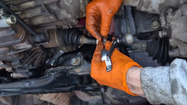
In the wheel well, remove the outer tie rod end nut and press out the tapered stud with the tie rod end puller without hammering the threads or tearing the boot. Next, disconnect the lower end of the sway bar link from the stabilizer bar by holding the stud with a 5 mm Allen and turning the nut with a 17 mmwrench.
Finally, remove the lower ball joint castle nut. If the taper is stubbornly seized (especially on cold days below 10 °C), apply WD-40 and gently warm the steering knuckle with a heat gun before giving it a side tap — in the video, heat released the ball joint immediately.
▶ at 12:40 in the video ↗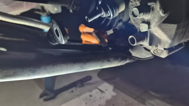
EPS Electrical Connectors, Rear Mount & Lowering the Subframe
Unplug the two electrical connectors on the EPS rack (one power and one signal/sensor plug, being careful not to stretch the wires while lowering). Remove the bolt from the rear engine mount (which only limits engine roll; the engine remains supported by the two side mounts).
Support the subframe on the floor jack, remove the 4 main bolts (17 mm / 19 mm — note that the rear bolts are longer than the front ones), lower slowly while guiding the U-joint free at the top, and slide the assembly (~30 kg) out through the driver-side wheel well.
▶ at 19:40 in the video ↗Step-by-Step — Middle: Bench Work, Bushing Swap & Viemar Inner Tie Rods
Washing with Impact, Counting Turns & Removing Inner Tie Rods
Wash all grease and road grit off the subframe outside the car (in the video, with Vonixx Impact 5:1 and detergent). Before loosening the outer tie rod ends, hold the shaft with a 14 mmwrench, loosen the 19 mm jam nut, and count the exact turns as you unscrew them (in the video: 21,5 turns on the right and 19,5 on the left).
Remove the boots (if intact, wash them for reuse) and unthread the inner tie rods using a 22 mm wrench counter-holding the rack bar and a 30/32 mm wrench on the inner tie rod body.
▶ at 27:00 in the video ↗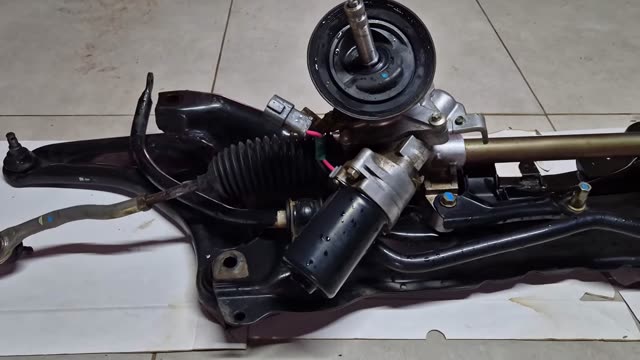
Replacing the Internal Steering Rack Bushing in the Vise (Zero Hassle)
Video pro tip: instead of struggling to release the 3 bushing locking tabs while the rack is bolted to the subframe, remove the 14 mm bolts securing the rack to the crossmember and take the clean rack over to the bench vise.
Slide the rack bar toward the opposite side, release the 3 tabs with a thin flat-blade screwdriver, pull out the cracked bushing (real dimensions measured with a caliper: OD 29,74 mm, height 15 mm, ID 23,7 mm), generously grease the rack teeth and shaft, compress the locking tabs of the new Auto Flag bushing with a hose clamp, and push it in straight using a 22 mm socket until it clicks into all three holes. Immediate result: zero play!
▶ at 35:00 in the video ↗Installing Viemar Inner Tie Rods (7,5 kgf·m), Boots & Copper Grease
Clean the internal threads of the rack bar with contact cleaner, apply threadlocker , and install the new inner tie rods (Viemar 6802111 right / 680313 left) torqued to 7,5 kgf·m while counter-holding the rack bar with the 22 mm wrench. Bolt the rack back onto the crossmember (4,5 kgf·m and 5,0 kgf·m).
Reinstall the boots with the new clamps, apply a light coat of copper grease to the outer threads (so they do not seize with rust during alignment), and thread the tie rod ends back on by the exact number of turns recorded.
▶ at 43:00 in the video ↗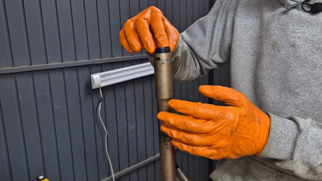
Step-by-Step — End: Raising the Subframe, Official Torques & Road Test
Lifting on the Floor Jack, EPS Connectors & Seating the U-Joint
Clean both EPS connectors with contact cleaner, balance the assembly on the floor jack, and raise it while aligning the interior U-joint splines with the marks made at the start. Start the 4 subframe bolts by hand (snugged only, no final torque yet) and reinstall the rear engine mount bolt.
Do not forget: reconnect both electric power steering plugs before lowering the car!
▶ at 50:50 in the video ↗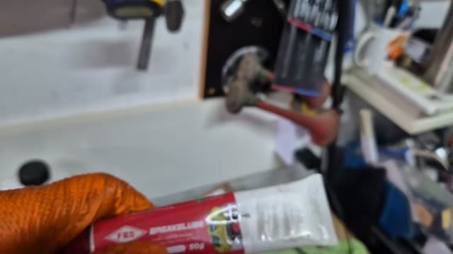
Suspension Torques (4,4 / 3,9 / 5–6 kgf·m), U-Joint (2,8 kgf·m) & Subframe (9,5 kgf·m)
Apply the confirmed torques with a torque wrench: outer tie rod end at 4,4 kgf·m, sway bar link at 3,9 kgf·m, lower ball joint between 5,0 and 6,0 kgf·m (aligning the cotter pin hole), and interior U-joint at 2,8 kgf·m (28 N·m).
Mount the wheels, rest the car on blocks/floor with its weight on the tires (and the safety jack 1 cm below the subframe), and apply the final torque of 9,0 to 9,5 kgf·m to the subframe bolts and 11 kgf·m to the wheel lug nuts.
▶ at 59:10 in the video ↗Cleared Checklist, Cobblestone Road Test & Final Alignment
Double-check the entire masking-tape checklist (including outer tie rod jam nuts and EPS connectors) before driving. If you notice a slight initial click in the U-joint when steering while stationary, slightly loosen the two 10 mm bolts, turn the wheel lock-to-lock to seat the splines, and re-torque to 2,8 kgf·m — in the video, the click vanished immediately.
On the cobblestone street test, the old "samba school" rattle disappeared completely. Finish by taking the car for a wheel alignment and geometry check at a specialist shop.
▶ at 67:30 in the video ↗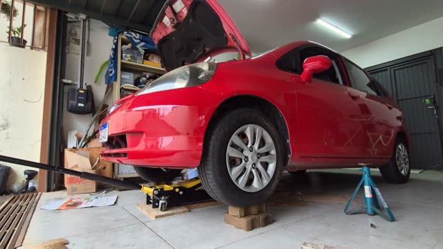
Post-Service Verification Checklist
- No EPS warning light on the cluster: Electric power steering feels light and smoothly assisted right after startup.
- Masking-tape checklist 100% crossed off: Wheels (11 kgf·m), subframe (9,5 kgf·m), tie rod jam nuts, sway bar links, ball joints (with cotter pins), and U-joint (2,8 kgf·m).
- Alignment scheduled: Even after counting tie rod turns, get a computerized wheel alignment right after the job.
Frequently Asked Questions (FAQ)
What is the most common cause of a sharp front-end clunk on the Honda Fit that does not go away after replacing shocks?
It is play in the internal steering rack bushing (passenger side, dimensions OD 29,74 mm × height 15 mm × ID 23,7 mm), often accompanied by play in the inner tie rods. When the bushing dries out or cracks, the rack bar knocks directly against the housing on rough roads.
Do you really need to lower the entire subframe to replace this Fit bushing?
Yes, it is the cleanest and safest route. Trying to swap the bushing in-car with the rack still mounted almost always tears the dust boot or damages the locking tabs on the new bushing, and prevents proper greasing of the rack bar.
Why can't you turn the steering wheel with the U-joint disconnected?
Because inside the steering column sits the Clock Spring (airbag and horn spiral cable), which has an exact limit of turns in each direction. Turning the uncoupled wheel off-center snaps the internal ribbon and triggers the airbag warning light on the dash.