


This page centralizes all technical documentation, the 12 complete high-resolution electrical diagrams and the video series for converting my Chevrolet S10 2.2 EFI (1996) to a Speeduino ZEQ-PRO39P-V4.0 programmable ECU. New episodes, TunerStudio tuning sessions and updates will be added here as the garage build progresses.
Project Architecture — S10 2.2 EFI (1996) + Speeduino
- Programmable ECU: Speeduino ZEQ-PRO39P-V4.0 (39-way) with Bluetooth module and idle air control (IAC).
- Firewall Bulkhead: Waterproof 33-way CF33 connector (cavities 01–30 + G1–G2) separating cabin and engine bay.
- Power Distribution: DNI 320005 box with 6 relays (R1–R6), 8 blade fuses (F1–F8) and 3 feeders of 6,0 mm² via 40A Midival fuses at the MTA battery terminal.
- Air-Fuel Monitoring: ZEQ-WBO2-V2.0 Wideband controller + Bosch LSU 4.9 sensor with 4x0,5 mm² shielded cable (105°C).
- Viewing Tip: Click any diagram below to open it full-screen with zoom and step through all 12 schematics with the arrow keys.
Quick Index of All 12 Electrical Diagrams
Scroll horizontally to see all table columns.
| # | Category | Diagram (click to jump) |
|---|---|---|
| 01 | Overview | 01. Wiring Harness Branch Topology Map |
| 02 | Main Connectors | 02. ECU Connector Pinout ZEQ-PRO39P-V4.0 (39-Way) |
| 03 | Main Connectors | 03. Firewall Bulkhead Connector CF33 (33-Way) |
| 04 | Relay and Fuse Box | 04. DNI 320005 Relay and Fuse Box (Top View) |
| 05 | Relay and Fuse Box | 05. Bottom Wiring and Crimping View — DNI 320005 |
| 06 | Individual Relay Diagrams | 06. Main Relay R1 — Clean Electronics (~3,7 A) |
| 07 | Individual Relay Diagrams | 07. Combustion Relay R2 — Fuel Pump, DIS and Injector (~12,8 A) |
| 08 | Individual Relay Diagrams | 08. A/C Compressor Relay R5 (~4,0 A) |
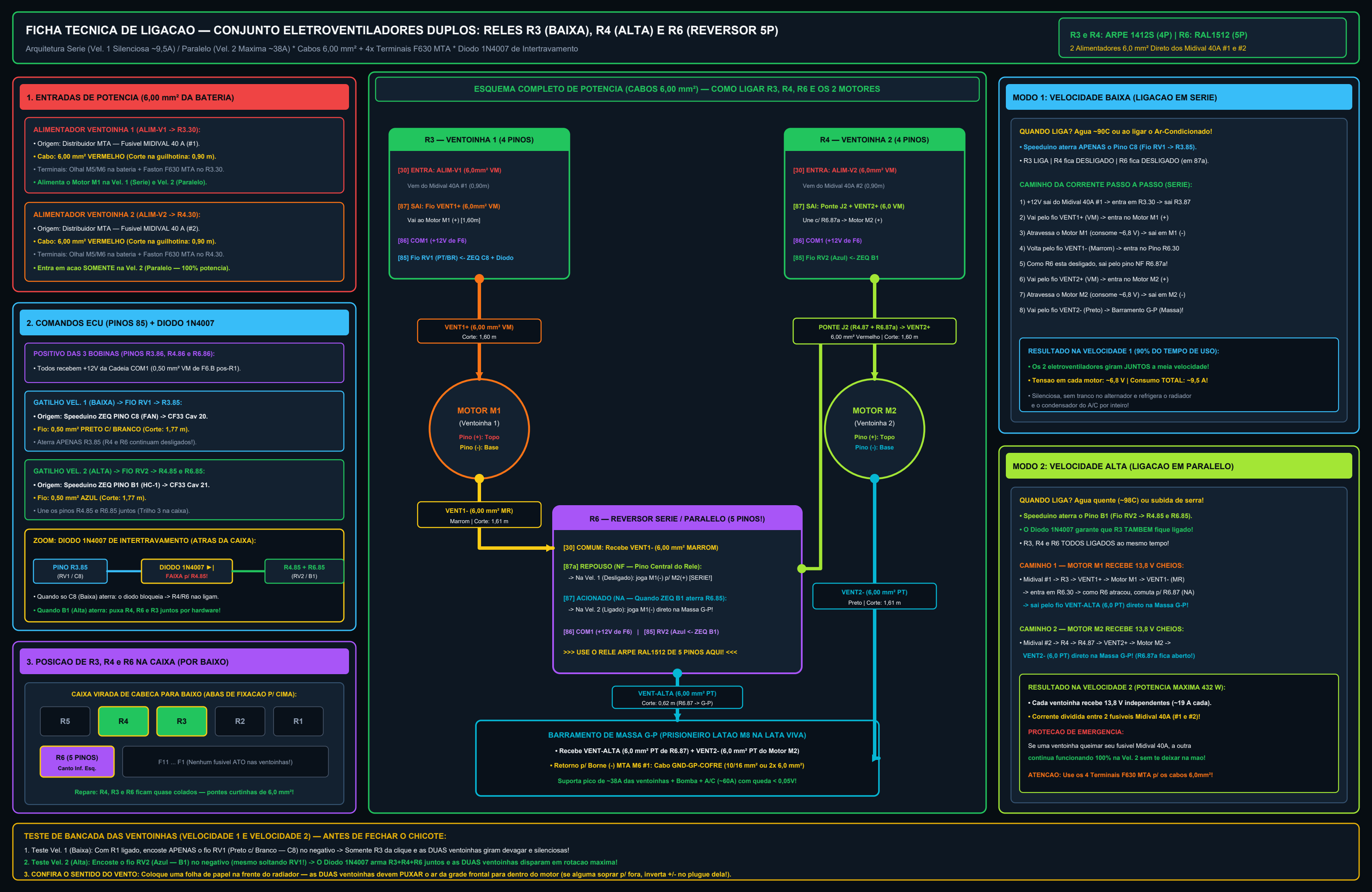
| 09 | Individual Relay Diagrams | 09. Cooling Fan Relays R3, R4 and R6 (Series / Parallel) |
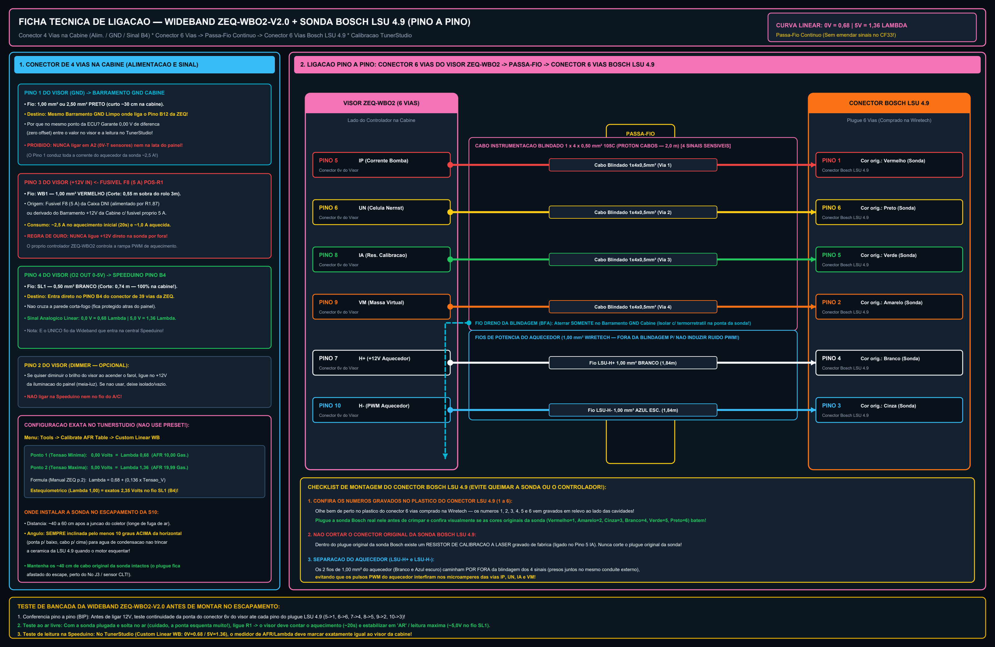
| 10 | Sensors and Instrumentation | 10. ZEQ-WBO2-V2.0 Wideband + Bosch LSU 4.9 Sensor |
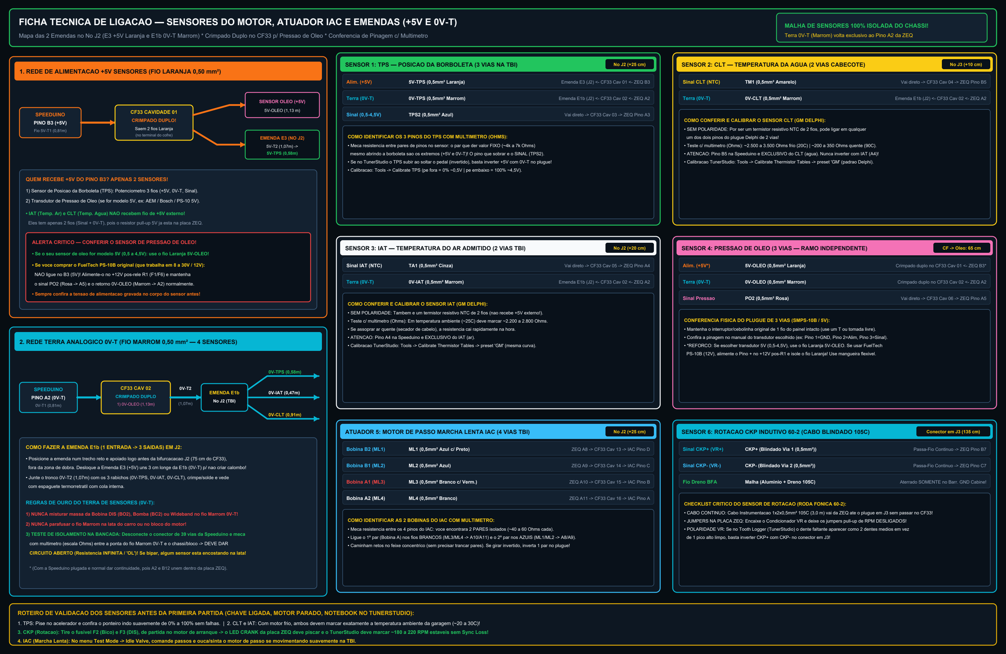
| 11 | Sensors and Instrumentation | 11. Engine Sensors, IAC Valve and +5V / 0V-T Splices |
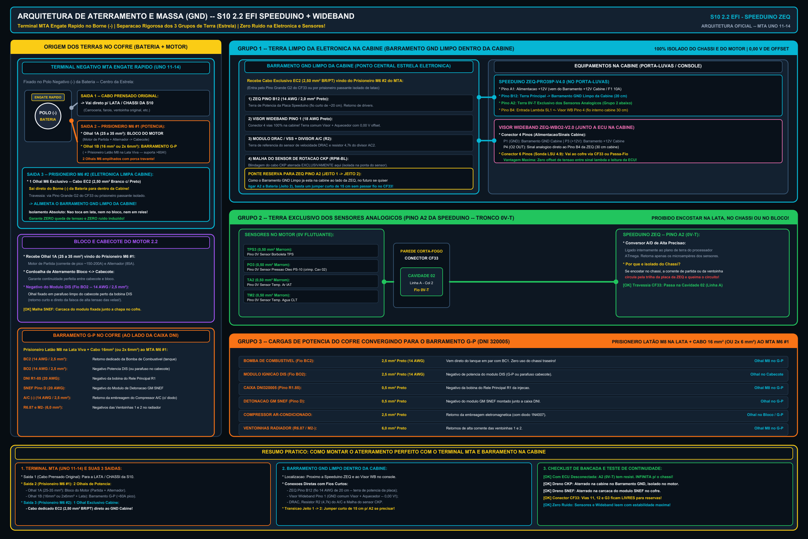
| 12 | Grounding and Chassis Earth | 12. Star Grounding and Earth Architecture |
Overview
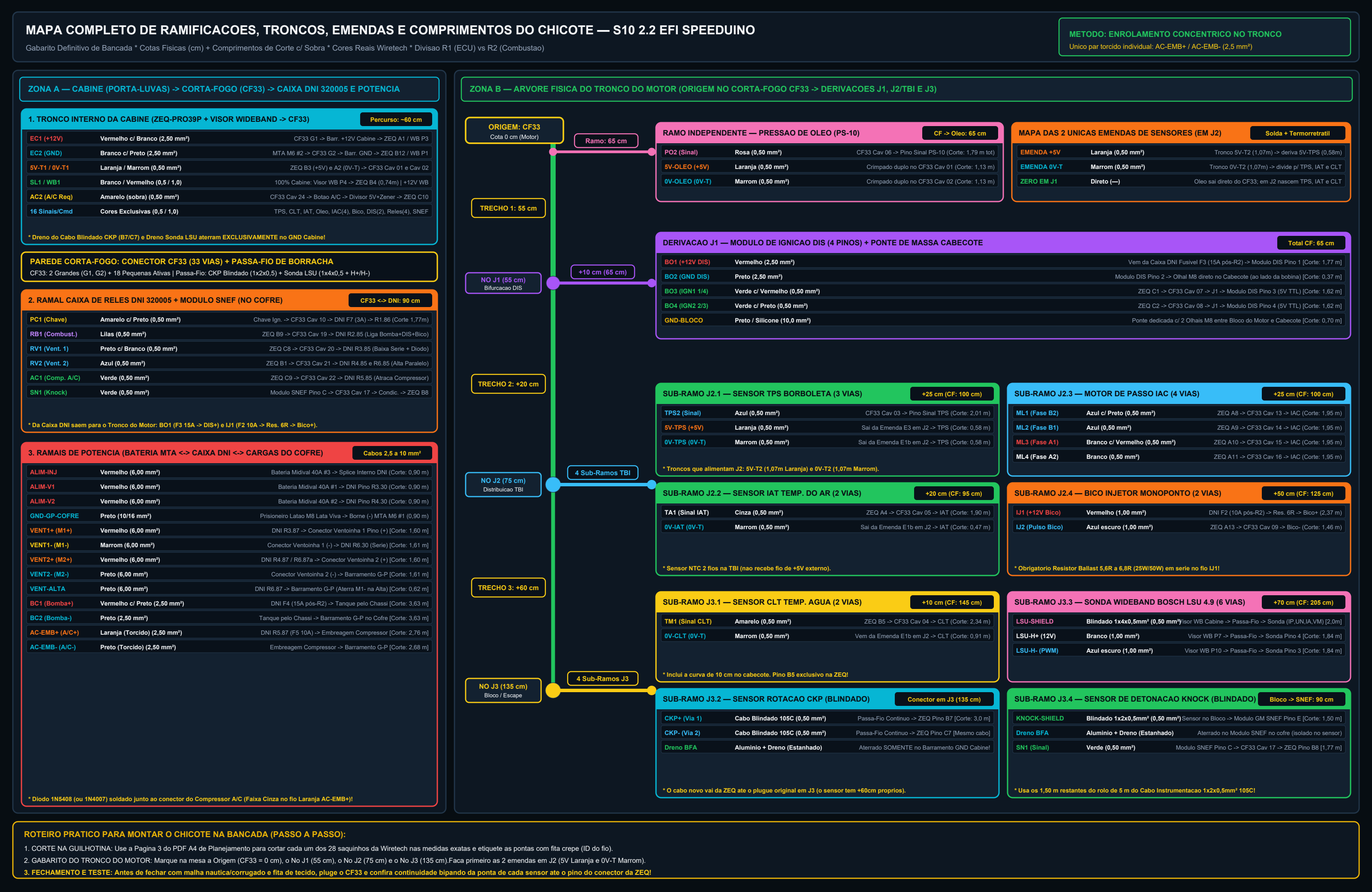
01. Wiring Harness Branch Topology Map
Complete wiring harness topology for the S10 2.2 EFI Speeduino: cabin, CF33 firewall bulkhead, engine trunk (Branches 1, 2 and 3), DNI 320005 relay box, MTA battery terminal and cooling fans.
Main Connectors (39P ECU and CF33 Firewall)
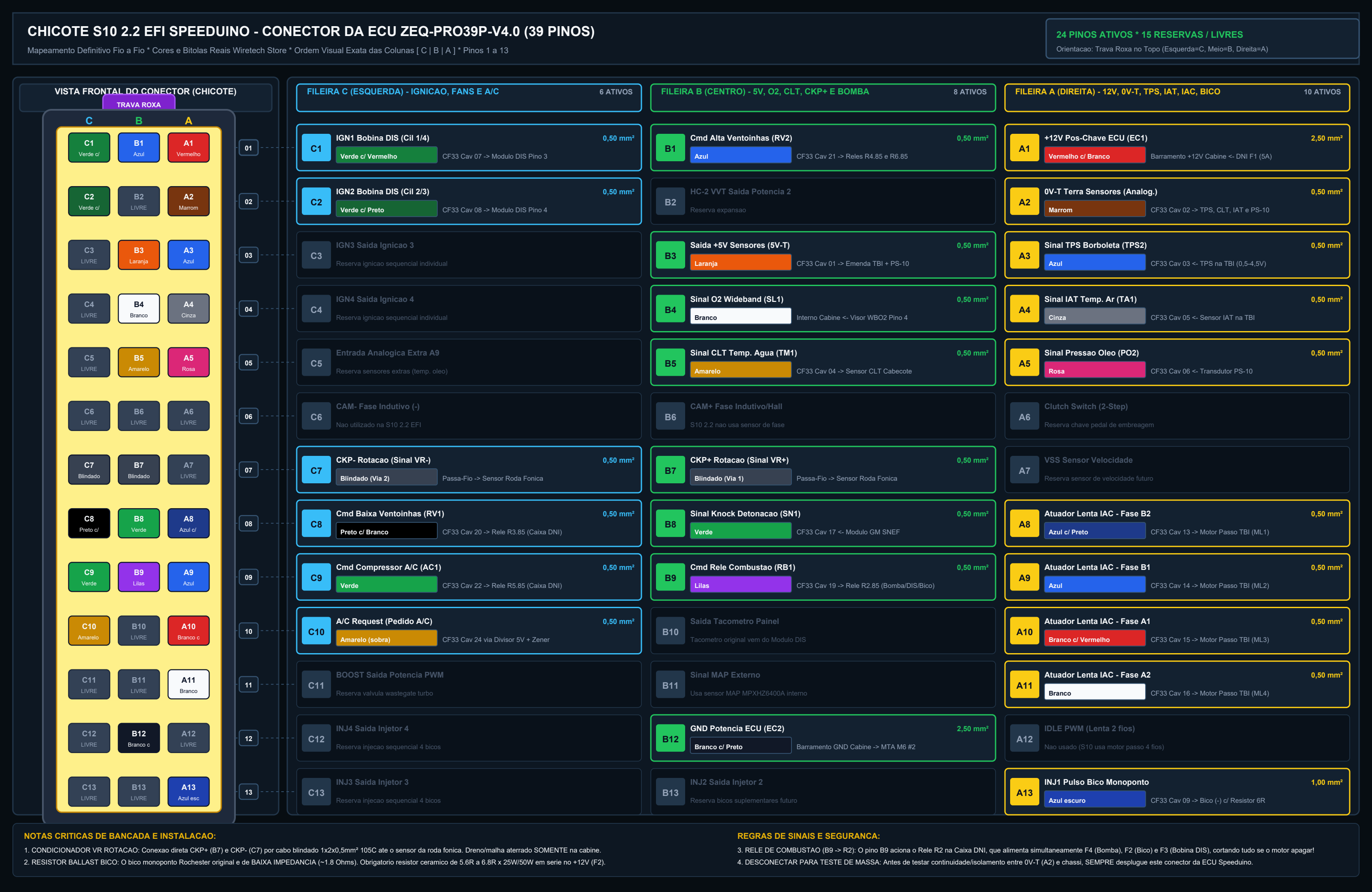
02. ECU Connector Pinout ZEQ-PRO39P-V4.0 (39-Way)
Pin-by-pin map of all 3 rows (C1–C13, B1–B13, A1–A13) with real Wiretech wire colors, electrical functions, sensor inputs and power outputs.
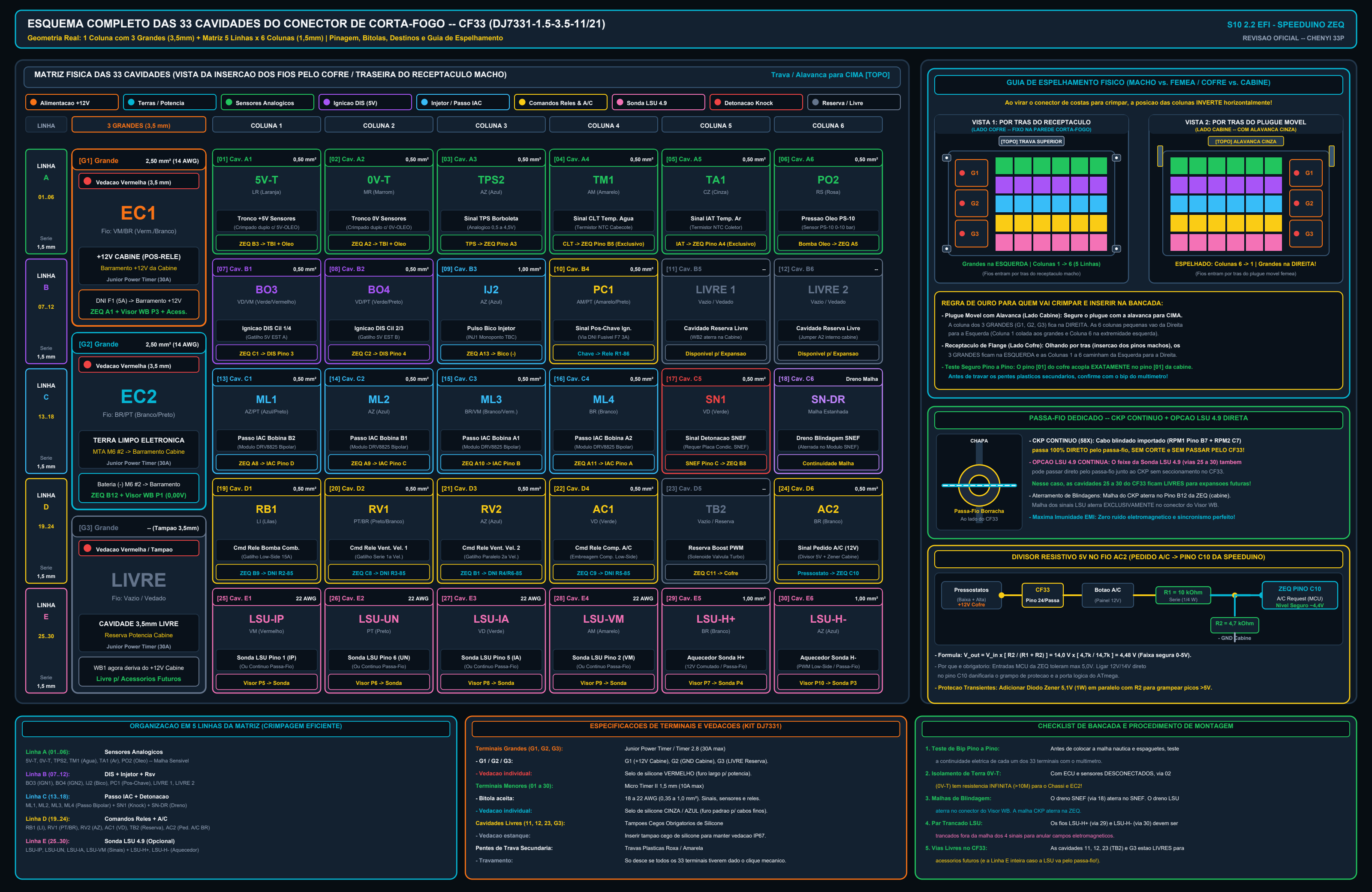
03. Firewall Bulkhead Connector CF33 (33-Way)
Full mapping of small cavities (01–30) and large cavities (G1–G2) across the Cabin and Engine Bay bulkhead, including double crimps and spare pins.
DNI 320005 Relay and Fuse Box
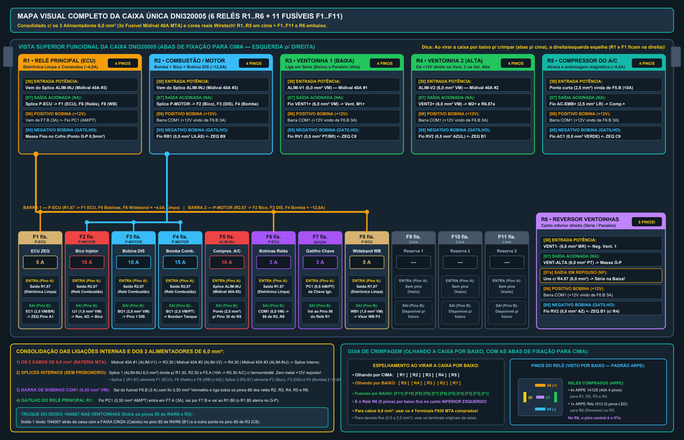
04. DNI 320005 Relay and Fuse Box (Top View)
Overall architecture of the 6 relays (R1–R6), 8 blade fuses (F1–F8), 3 feeders of 6,0 mm² from the 40A Midival fuses at the MTA battery terminal, and the 3 insulated internal splices.
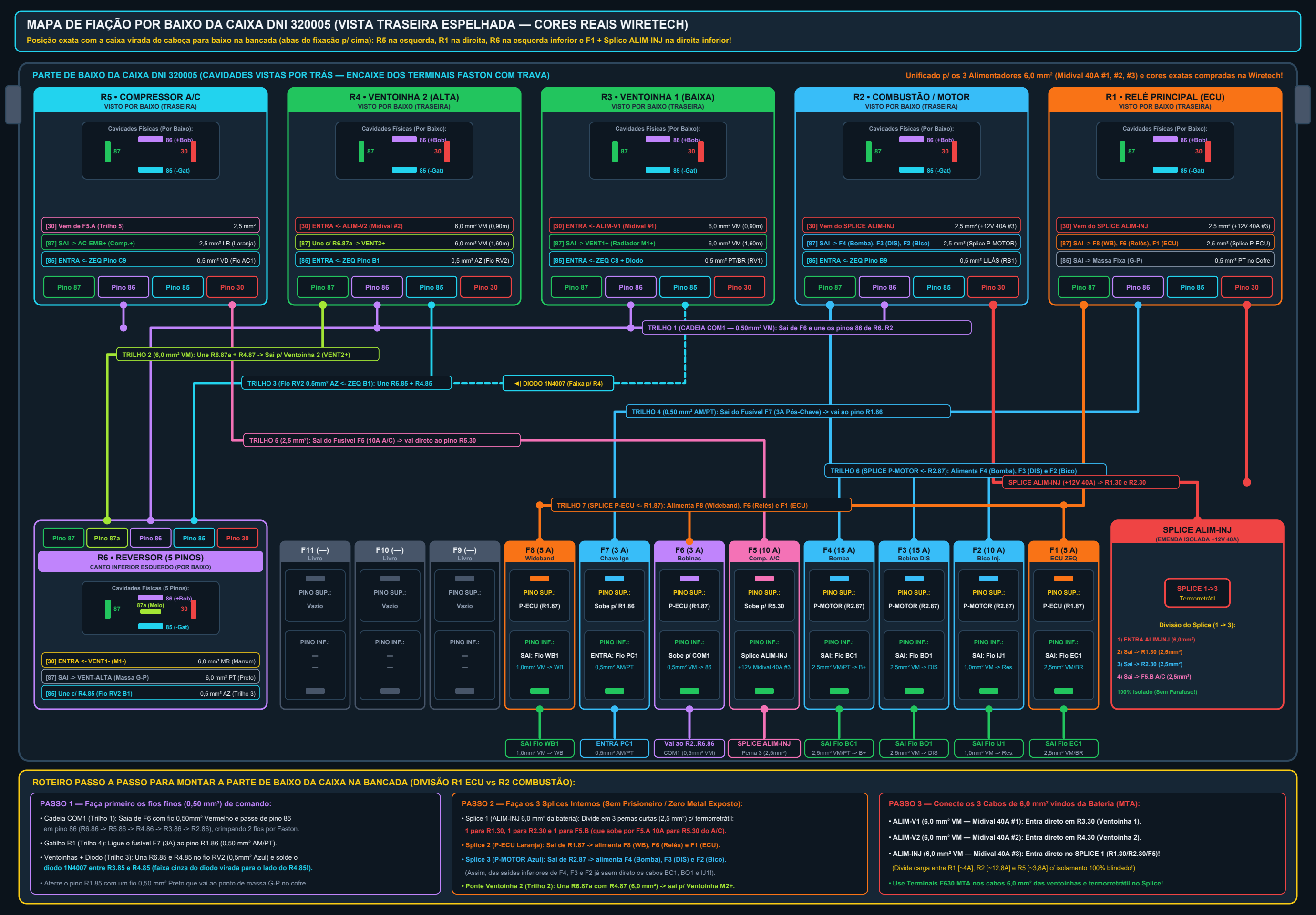
05. Bottom Wiring and Crimping View — DNI 320005
Underside assembly map of the DNI box with true mirrored relay and fuse sockets, internal jumpers and distribution of the 3 splices.
Individual Relay Diagrams (R1 to R6)
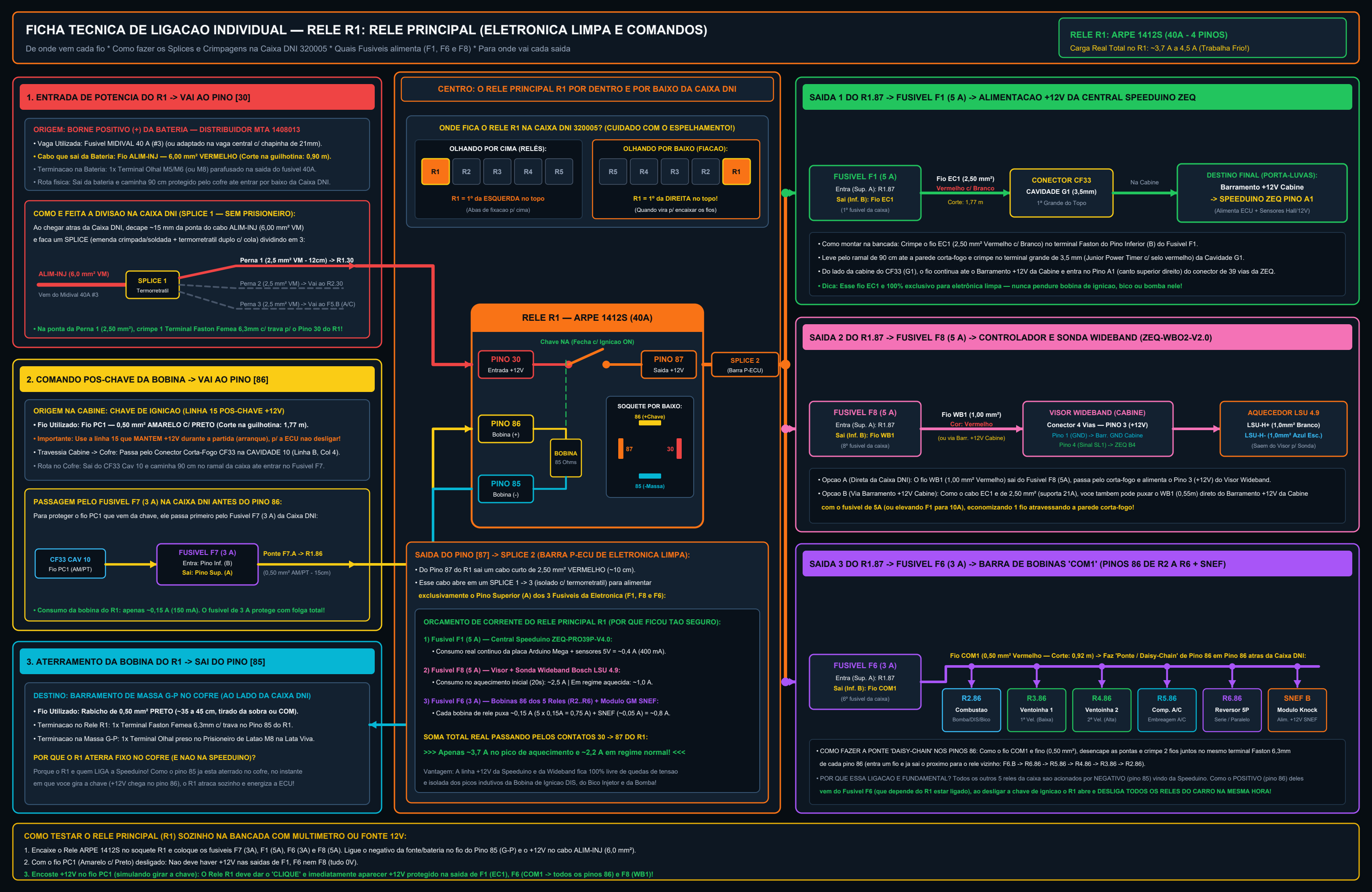
06. Main Relay R1 — Clean Electronics (~3,7 A)
End-to-end detail of Main Relay R1 (ignition-switched F7 to R1.86, ALIM-INJ to Splice 1 and R1.30, output R1.87 to Splice 2 feeding F1 ECU, F8 Wideband and F6 Coils).
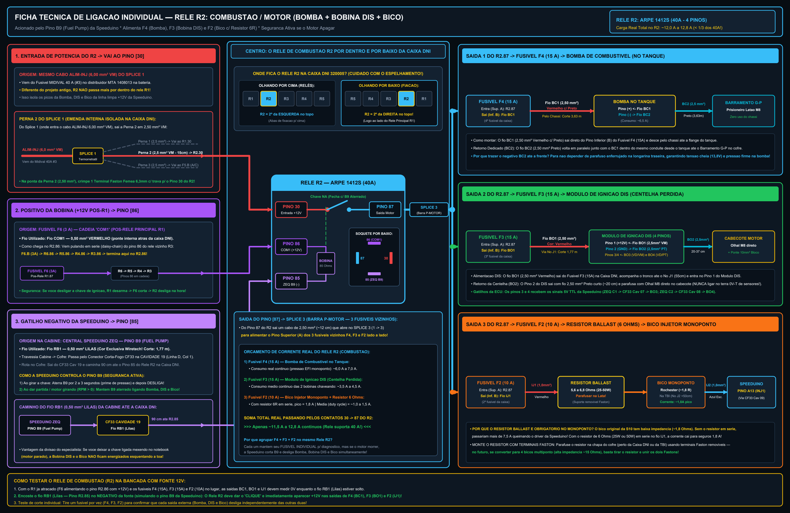
07. Combustion Relay R2 — Fuel Pump, DIS and Injector (~12,8 A)
Driven by the ECU (ZEQ B9) with safety shutoff if the engine stalls: R2.87 to Splice 3 feeding F4 (Fuel Pump 15A), F3 (DIS Module 15A) and F2 (Injector 10A + 6Ω/50W Resistor).
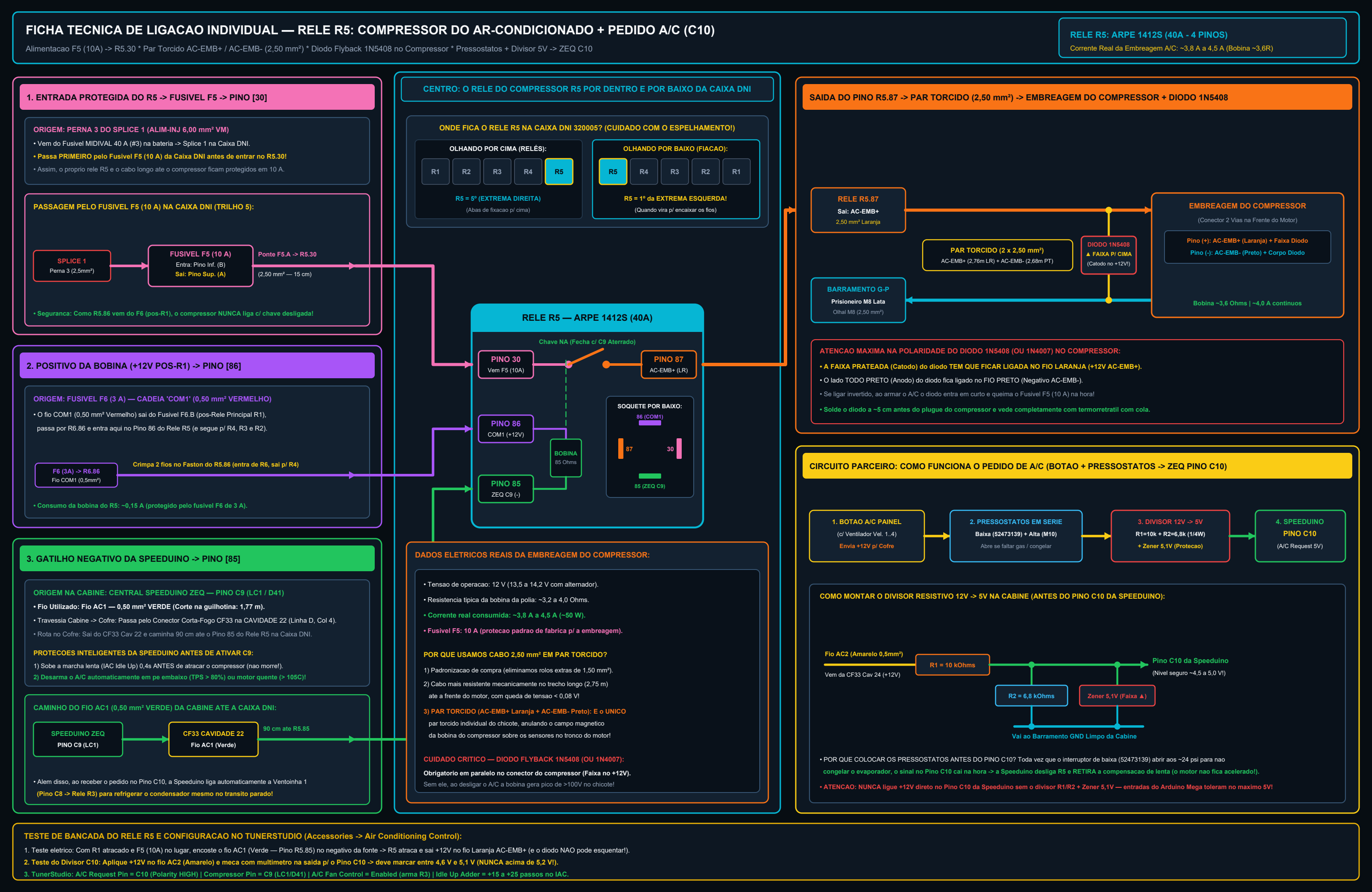
08. A/C Compressor Relay R5 (~4,0 A)
Power via F5 (10A), control ZEQ C9, A/C request via 5V divider (ZEQ C10) and twisted-pair output AC-EMB+/AC-EMB- (2,50 mm²) with 1N5408 flyback diode.
09. Cooling Fan Relays R3, R4 and R6 (Series / Parallel)
2-speed fan control on 6,00 mm² cables: quiet Speed 1 in series (~9,5 A) and maximum Speed 2 in parallel (~38 A), with 2 independent 40A Midival fuses.
Sensors, IAC Valve and LSU 4.9 Wideband
10. ZEQ-WBO2-V2.0 Wideband + Bosch LSU 4.9 Sensor
Pin-by-pin gauge pinout, 4x0,5 mm² shielded harness (105°C), heater routed outside the shield, warning about the laser-trimmed calibration resistor in the OEM plug, and TunerStudio calibration.
11. Engine Sensors, IAC Valve and +5V / 0V-T Splices
+5V and 0V-T distribution (double crimp at CF33 + E3/E1b splices at J2), pinout for TPS, CLT, IAT, PS-10 (5V vs 12V warning), 4-wire IAC and shielded CKP.
Star Grounding and Earth Architecture
12. Star Grounding and Earth Architecture
Strict separation between Clean Electronics Ground (Cabin GND Busbar to MTA Battery M6 #2) and Power Ground (Brass M8 Stud G-P Busbar to MTA M6 #1 + Block/Head Strap).
Video Series — Speeduino on the S10 2.2 EFI
Follow all published episodes of the build below in chronological order. New episodes (harness assembly, engine bay installation, first start and tuning) will be added here as they go live:
- Episode 1 (12/10/2026) — Programmable ECU on the S10 2.2 EFI — Why I chose Speeduino and initial planning
- Episode 2 (29/10/2026) — Speeduino Programmable ECU on S10 — Bench overview of parts (Zack Speed ECU, Wideband, DNI Box and CF33 Connector)
- Episode 3 (09/11/2026) — Speeduino on S10 2.2 EFI — Engine bay measurements and cardboard wiring harness layout