


The McPherson independent front suspension of the 1st generation Ford Ka (1997 to 2007) is fitted both to the early models with the Endura-E (1.0 and 1.3) and to the later phase with the Zetec Rocam (1.0 and 1.6) — it is known for its agile handling, but demands thorough periodic maintenance. When worn, it produces dull clunks, steering play, uneven tire wear, and irritating noises at the strut tower.
This guide brings together in one complete technical procedure from start to finish the practical procedures performed by Paulo in the garage workshop, unifying the 6 episodes dedicated to the front end of the 1998 Ka: symptom diagnosis, exact wrench list and sizes, vehicle disassembly, bench service with coil spring compressors, control arm replacement, and the essential secret of top plate alignment and final torquing with suspension settled.
Safety First
- Mandatory Support on Jack Stands: Never work under a car supported solely by hydraulic jacks. Position mechanical load-rated jack stands under the frame rails or designated structural unibody lift points, and chock the rear wheels.
- Critical Warning on Coil Spring Compressors: McPherson suspension coil springs store immense elastic potential energy. Always use a quality pair of compressors with sound retaining jaws, positioned strictly on opposite sides at 180°, tightening the threaded rods slowly and evenly. Never point the spring trajectory toward your body or face during compression or release.
Symptom and Play Diagnosis on the Ford Ka Front End
Before taking components apart, conduct a thorough inspection with the vehicle on the ground and then raised. The most common issues on the 1997–2007 Ka front end are very typical:
- Dull knocking ("thump-thump") on uneven pavement or cobblestones: Classic symptom of a collapsed/crushed upper strut mount, sway bar end links with play in plastic ball sockets, or play in the steering knuckle ball joint pin.
- Top plate rubbing against the tower sheet metal (or stiff steering with clicks): In the engine bay, the rubber-coated metal top plate must maintain clearance from the strut tower sheet metal. When the rubber mount gives way or the upper axial bearing binds, the plate drops and rubs directly against the metal, preventing the strut rod from rotating smoothly during steering and causing metal squeals and heavy steering return (as diagnosed in Front Suspension Noise).
- Instability during hard braking or sudden acceleration: Play in the rear control arm bushings (known as boomerang bushings). When the vulcanized rubber tears, the control arm wobbles on the subframe, altering dynamic toe and causing the car to dart unpredictably to one side.
- Steering play and off-center steering wheel: Torn dust boots and axial play in the tie rod ends threaded onto the steering rack inner tie rod.
 ▶ 02:00Diagnosis: Knocking Noises and Collapsed Strut Mount ▶ 07:30Inspecting Top Mount Clearance in the Tower
 ▶ 04:21Height Difference in the Top Mount Cap
 ▶ 02:11diKa: Why the Top Plate Must Not Touch
Table of Wrenches and Tools Used in the Videos
To complete the entire job without interruptions in a home garage, prepare beforehand the tool kit with the exact dimensions documented by Paulo across the series:
Scroll horizontally to see all table columns.
| Tool | Size / Specification | Application on Ford Ka | Workshop Tip |
|---|---|---|---|
| Lug wrench / Socket | 19 mm (hexagonal) | Wheel lug nuts | Break torque 1/2 turn while tires are still on the ground before lifting |
| Open-end / Combination wrench | 18 mm (or 19 mm depending on the nut) | Strut rod top nut / control arm bushing nut | Used in combination with the Allen key so the central rod does not rotate |
| Allen key (hex) | 6 mm | Center hex socket at the tip of the strut rod | Holds the rod stationary while the 18 mm box/open wrench loosens the nut |
| Torx Bit + Socket | Torx T50 / T51 | Steering knuckle ball joint pinch bolt | Clean the head recess thoroughly with a wire brush before applying force |
| Wrench / Socket | 17 mm and 19 mm | Ball joint bolt nut and tie rod end nut | Hold locknut while turning the Torx bolt |
| Sockets / Wrenches | 15 mm and 18 mm | Control arm bushing mounting bolts to subframe and strut clamp bolt | Bottom bolt is 15 mm and upper nut through the subframe is 18 mm |
| Coil Spring Compressor | Pair of threaded spindle rods with dual hook jaws | Front coil spring compression on the workbench | Position jaws at 180° with lubricated threads for smooth travel |
| Pry Bar and Breaker Bar | Steel pipe / bicycle handlebar / crowbar | Leverage arm to release control arm bushings and disengage knuckle | Paulo improvised a sturdy steel bicycle handlebar as a rigid breaker bar |
| Hammer / Mallet | Medium mechanic's ball-peen hammer | Controlled side taps on the steering knuckle collar | Breaks accumulated rust without denting the cylindrical housing |
| Workshop Supplies | Penetrating oil, H7 degreaser, masking tape | Engine bay paint protection and wheel well cleaning | Masking tape on the tower lip prevents wrench scratches on body paint |
Parts List for the Ford Ka Front Assembly
Below are the components that make up the complete front-end overhaul and purchasing recommendations noted in the episodes:
- Front Shock Absorbers (Pair): Gas/oil pressurized units specific to the 1st generation Ford Ka. During teardown of the 1998 Ka, the old shock was completely blown, with zero hydraulic stroke resistance and no rod rebound (see test at 14:43).
- Complete Front Control Arm (Wishbone with Bushings and Ball Joint): In episode 2, Paulo chose to purchase complete brand-new control arms (Cofap) rather than just pressing in new bushings, due to micro-fissures in the stamping and the excellent value of factory-vulcanized boomerang bushings and pre-fitted ball joints.
- Upper Strut Mounts with Axial Bearing: Heavy-duty structural rubber mount with integrated axial ball bearing. The bearing is essential to allow the entire strut assembly to rotate freely during wheel steering.
- Polyurethane Bump Stop and Dust Boot Kit: The PU foam bump stop prevents metal-on-metal bottoming out of the shock against the tower, and the boot shields the chrome rod from flying stones, dust, and water that destroy the oil seal.
- Strut Top Caps: Protective steel discs with bonded finish rubber installed in the engine bay. Critical note: aftermarket versions exist on the market with center tube heights different from OEM (requiring trimming ~1 cm to prevent binding the suspension).
- Tie Rod Ends (Pair): Ball-jointed tie rod ends threaded onto the manual steering rack rods, essential for eliminating play and preserving alignment.
- Stabilizer Bar Link Rods: Fitted to Ka versions equipped with an anti-roll bar (1.3 Endura models and Zetec Rocam family). Base 1.0 Endura models may not be factory-equipped with a front stabilizer bar.
 ▶ 21:13Blown Shock Absorber Assessment ▶ 22:19New Strut Mount and Bearing ▶ 23:14New Complete Cofap Control Arms ▶ 25:55New Tie Rod Ends
Phase 1: Lifting and Releasing Wheel Peripherals
Disassembly should be initiated with the vehicle still resting on the ground to take advantage of vehicle inertia:
Step 1: Initial loosening on the ground and safe support on jack stands
With the wheels still on the pavement, fit the 19 mm lug wrench and break the torque on each of the four front wheel bolts by half a turn. Next, open the engine hood, insert the 6 mm Allen key into the center of the strut rod, and use an 18 mm combination wrench to back off the top nut by 1 to 2 turns (at 01:02 of video 1/4). Do not remove the nut completely yet!
Position the hydraulic floor jack under the structural jacking point, raise the front of the Ka, place the two jack stands under the frame rails and gently lower the car's weight onto them. Fully remove the lug bolts and take off both front wheels.
Step 2: Disconnecting the stabilizer link and the tie rod end
If the vehicle is equipped with a front sway bar, loosen the lower stabilizer link nut on the control arm or strut using a 15 mm or 17 mmcombination wrench. Next, locate the tie rod end attached to the steering knuckle. Apply penetrating oil to the exposed threads and remove the castle/nyloc nut using a 17 mm wrench (at 09:33).
To separate the tie rod conical pin from the steering knuckle without tearing the rubber dust boot or damaging the threads, use a universal ball joint/tie rod puller. If you do not have a puller, strike the side boss of the steering knuckle firmly and squarely with a hammer while applying downward pry tension beneath the rod; the shock vibration will pop the taper out.
Step 3: Removing the ball joint pinch bolt and strut lower clamp bolt
At the bottom of the steering knuckle, the ball joint pin is locked in place by a transversal pinch bolt. Clean the center recess of the bolt head with a wire brush to dislodge dirt and rust. Firmly seat the Torx T50 or T51 bit into the bolt head and counter-hold the 19 mm (or 17 mm) nut on the opposite side using a combination wrench (at 04:09). Rotate the wrench until the nut is removed and tap the bolt out using a brass punch.
Just above, loosen and remove the pinch bolt that clamps the split collar of the steering knuckle around the strut housing.
 ▶ 01:02Loosening the Wheel and the 18 mm Nut ▶ 04:09Loosening the Ball Joint Torx T51 Bolt ▶ 06:51Difficulty with the Tie Rod End ▶ 09:33Loosening the Tie Rod with 17 mm Nut
Phase 2: Removing the Control Arm (Wishbone) and McPherson Strut Assembly
With peripheral linkages disconnected, the assembly has enough mobility to extract the control arm and strut column:
Step 4: Removing control arm subframe bolts and bench inspection
The Ford Ka front control arm is anchored to the subframe by two primary bolt assemblies tightened to high factory torque. The front horizontal bolt is accessed from underneath with a 15 mmsocket/wrench, while the rear vertical bushing bracket features an upper nut of 18 mm passing through the chassis frame (at 15:24).
To break loose seized factory bolts, use a long breaker bar with an extension. In the video, Paulo slipped a sturdy steel bicycle handlebar over the ratchet handle to increase leverage without rounding the bolt heads. Once both fasteners are out, pry the control arm ball joint stud down out of the knuckle and take the complete arm to the bench for inspection.
On the bench (at 19:30), the passenger-side rear boomerang bushing was found to be thoroughly crumbled and separated from its steel center core, confirming the necessity of immediate replacement.
Step 5: Decoupling the steering knuckle and removing the McPherson strut
With the ball joint pin disengaged, support the steering knuckle on a wooden block so that the weight of the brake rotor and caliper does not pull on the flexible rubber brake hose or dislodge the inner CV axle tripoid from the transmission.
Liberally spray penetrating oil into the knuckle clamping slit around the shock tube. With a medium hammer, deliver calibrated, solid blows to the knuckle collar casting to shock the joint and break the rust bond (at 05:27). Insert a heavy pry bar at the lower joint and pry the knuckle downward smoothly until the shock cylinder slides all the way out of the knuckle.
Reach into the engine bay, support the strut assembly from underneath inside the wheel well with one hand, and fully remove the top 18 mm nut and plate with your other hand. Lower the complete McPherson strut assembly with its coil spring and withdraw it through the wheel arch.
▶ 05:27Controlled Taps and Pry Bar ▶ 13:05Improvised Breaker Bar for Loosening ▶ 15:24Loosening the 15 mm and 18 mm Bushings ▶ 19:30Inspection of the Torn Boomerang Bushing Phase 3: Bench Work — Spring Compressor, Strut Mount, and Top Plate
Bench operations require the utmost mechanical precision and strict adherence to safety protocols:
Step 6: Clamping the strut in the vise and symmetrical coil spring compression
Secure the strut lower mounting clevis/bracket in the bench vise (never clamp the cylindrical damper tube directly, as that will dent and destroy the internal cylinder). Apply a thin layer of grease or engine oil to the threads of both spring compressor lead screws to prevent binding under heavy load.
Position both compressors directly opposite each other at 180° along the coil spring perimeter (at 05:28 of video 3/4). With a ratchet and 19 mmsocket, tighten 4 to 5 turns on one spindle and then 4 to 5 turns on the opposite spindle. Repeat this alternation patiently until the spring shortens enough to lose pressure contact against the upper strut mount and the spring perch.
Step 7: Disassembling strut mount, bearing, and damper pressure testing
With the spring free of pressure against the top, insert the 6 mm Allen key into the center of the chrome rod tip and loosen the center retaining nut using the 18 mm box/combination wrench (at 11:05). Remove:
- The upper nylon locknut;
- The upper rubber strut mount with its integrated axial bearing;
- The upper steel spring seating dish (at 11:25);
- The coil spring (held compressed in the pair of spring compressors);
- The polyurethane foam bump stop and plastic piston rod dust shield boot.
Discarded Shock Absorber Diagnosis: In video 3/4 (at 14:43), Paulo demonstrates the manual test by compressing the original shock rod: the rod sank without offering any hydraulic resistance, fell freely under its own weight, and failed to return to the extended position — confirming that internal pressurized gas and hydraulic oil had completely leaked out.
Step 8: Quick Procedure / Golden Tip — Replacing the Top Mount Dish Directly from the Engine Bay
In videos ZzH-X6GkxVY and Ay9ncpktKAA, Paulo demonstrates a popular practical fix sought by Ford Ka owners: how to replace only the strut tower top cap dish without having to dismantle the complete suspension or use coil spring compressors!
- With the car on the ground: The front end weight keeps the spring fully compressed against the strut mount in the tower, so the rod neither drops down nor escapes.
- Paint protection: Apply masking tape all around the strut tower sheet metal lip inside the engine bay (at 01:48). When applying force with the
18 mmor19 mmcombination wrench, any accidental slip will hit the tape, preventing scratches to automotive paintwork. - Dimensional matching and center sleeve trimming: Paulo discovered that aftermarket replacement dishes sold on the market often feature a central metal sleeve approximately 1 cm longer than original Ford dishes (at 04:21). When fitted as supplied, the nut bottoms out on the metal tube before clamping down the rubber, resulting in vertical play and rattling clunks. Paulo solved this by using a hacksaw to shorten the sleeve to OEM dimensions and filing away burrs (at 08:53).
- Mandatory Clearance from Sheet Metal: As explained in the diKa (at 02:11), the upper dish MUST NOT sit flush against the tower sheet metal when the car rests on the ground. It must have a free clearance of approximately 5 to 10 mm. The dish's purpose is to prevent the strut from falling out if the vehicle goes over an abrupt drop or is raised on a shop lift; during everyday driving, it rotates together with the steering and must not rub against the sheet metal.
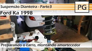 ▶ 05:28Spring Compression in the Vise ▶ 11:05Disassembling the Strut Mount and Bearing ▶ 01:48Masking Tape to Protect the Paint ▶ 08:53Adjusting and Cutting the Pipe Height ▶ 04:22Proper Torque and Rotational Clearance
Phase 4: Cleaning, Painting, and Reassembly on the Car
Before installing new components, execute a thorough cleaning to ensure everything seats flawlessly:
Step 9: Wheel well cleaning and strut assembly with new kit
Spray biodegradable cleaner degreaser (H7) inside the wheel wells, on the steering knuckle, and around the strut tower mount holes (at 00:40 of video 3/4). Scrub with a brush and nylon bristles, rinse, and dry thoroughly with clean shop towels.
To assemble the new strut column:
- Slide the new polyurethane bump stop and protective dust boot over the new damper rod;
- Seat the compressed spring onto the lower spring seat of the shock absorber. Crucial assembly point: the lower coil tail end must abut precisely against the stop contour formed into the welded spring perch (at 13:42);
- Position the upper steel spring seat dish and install the new strut mount with lubricated axial bearing;
- Install the washer and the self-locking nut on the shock rod. Thread the nut down while holding the
6 mmAllen key until it seats and take up firm initial tension; - Release the spring compressor spindles strictly alternating side to side and evenly, ensuring that both top and bottom coils seat squarely in their guide perches without slipping.
Step 10: Inserting the strut into the steering knuckle and McPherson tower
Feed the assembled strut up through the wheel well, guiding the threaded rod tip through the top tower hole in the engine compartment. Temporarily fit the top plate and nut to keep the strut from dropping.
At the bottom, align the shock body tube with the collar opening of the steering knuckle. Mandatory assembly detail: on the backside of the shock absorber there is a welded metal alignment tab/key that must enter squarely into the knuckle slot. The damper must slide down fully until it seats against the lower stop ledge of the knuckle. Install the knuckle pinch clamp bolt and snug it down finger-tight.
Step 11: Installing the new front control arm and locking the ball joint
Take the new control arm with pre-installed front and rear bushings. Fit the bushings into the vehicle's subframe brackets. Install the bolts— 15 mm underneath and 18 mm on top—threading them only loosely by hand (do not apply final torque at this stage!).
Next, steer the ball joint stud into the bore at the bottom of the steering knuckle. The conical ball joint pin features a machined pinch groove that must align with the cross bolt hole. Insert the Torx T51 bolt with washer and thread on the nut 19 mm on the other end. Tighten firmly, securing the ball joint stud into the knuckle. Reattach the tie rod end to the steering knuckle and reinstall the sway bar link rod.
▶ 00:40Washing and Cleaning with H7 Degreaser ▶ 13:42Correct Spring Seating on the Stop ▶ 14:43Final Assembly of the Ready Strut ▶ 04:09Pinch Slot and Ball Joint Pin Fitment Torquing Under Loaded Suspension, Final Checks, and Wheel Alignment
This is the step most frequently overlooked by inexperienced mechanics and the primary reason for premature failure of new bushings:
Step 12: The Golden Rule of Assembly — Torquing Suspension at Ride Height
The rubber bushings on the Ford Ka front control arm ( silentblockdesign) operate through torsional elastic twisting of the vulcanized rubber bonded between inner and outer steel sleeves. They never rotate freely like bearings.
Why you should never torque control arm bolts with the wheels hanging in the air:
If you lock down the control arm bushing bolts while the vehicle is suspended on jack stands (with wheels hanging in full droop), the elastomer is clamped in an extreme extension angle. When the car is set back down on the ground, the vehicle's weight will severely twist the rubber bushings at rest. Every speed bump or pothole will exceed the elastomer's elastic limit, causing brand-new bushings to tear and disintegrate in less than 3 to 6 months of use.
How to perform proper torquing in the garage:
- Hydraulic Jack Method: With the car safely resting on the jack stands for safety, place the floor jack with a protective wooden block under the steering knuckle or directly beneath the front ball joint housing. Pump the jack up, lifting the suspension until the chassis frame just barely begins to unload from the jack stand (attaining the exact resting ride height of the car).
- Final Torquing: With the control arm leveled at its neutral ride-height position, apply final torque using a breaker bar and sockets of
15 mmand18 mmon both front control arm bolts. Repeat the identical procedure on the opposite side.
Step 13: Wheel mounting, lowering to the ground, and top dish final tightening
Mount the front wheels and thread in the 19 mm lug bolts crosswise with moderate snugness to seat the wheels flush against the brake rotors. Jack up the front end, pull out the safety stands, and lower the Ford Ka gently until its full curb weight rests on all four tires on level ground.
With the vehicle on the ground:
- Apply final crosswise torque to the wheel lug bolts using a
19 mmsocket (recommended torque of approximately95 to 105 Nm); - In the engine compartment, apply final torque to the strut rod top nut (
18 mmor19 mm) while counter-holding the center with the6 mmAllen key (at 04:22 of the diKa); - Bounce the front end by pushing down firmly on the front fenders several times, and visually check the top dish gap: confirm there is a clearance of about 5 to 10 mm between the dish rubber and the painted strut tower, without rubbing against the sheet metal.
Step 14: Road test and computerized wheel alignment
Perform a short test drive over varying road surfaces (asphalt, cobblestones, and slight road dips). Pay close attention to:
- Whether the dull knocking noise has been completely eliminated;
- Whether steering effort is light and smooth in both directions without binding or harsh return;
- Whether the car tracks straight without pulling to either side.
Mandatory Wheel Alignment: Any suspension service involving the removal of control arms, struts, or tie rod ends alters wheel alignment geometry. Take the Ford Ka immediately to an alignment shop for a complete computerized alignment, checking caster and camber, and precisely adjusting the steering toe on the tie rod threaded adjusters. This will protect your tires against premature edge wear.
▶ 15:00Road Test and Absence of Noises ▶ 02:11Checking Top Mount Clearance ▶ 15:24Golden Rule: Torquing Under Load ▶ 14:43Front Suspension Assembled and Aligned Torque Specifications and Technical Tightening Table
Reference torque values for calibrated torque wrenches or equivalent professional tightening documented for the 1st generation Ford Ka front suspension:
Scroll horizontally to see all table columns.
| Fastener / Component | Specified Torque | Torquing Condition |
|---|---|---|
| Ball joint pinch bolt on steering knuckle (Torx T51 / 19 mm nut) | 50 to 55 Nm | Ensure ball joint pin pinch groove aligns with bolt shank |
| Strut clamp bolt on steering knuckle | 80 to 90 Nm | Strut tube must be fully seated against bottom guide stop of knuckle |
| Front control arm horizontal bolt on subframe (15 mm) | 60 to 70 Nm | Mandatory: tighten only with suspension loaded at neutral ride height |
| Rear boomerang bushing vertical bolt on subframe (18 mm) | 85 to 95 Nm | Mandatory: tighten only with suspension loaded at neutral ride height |
| Strut rod top nut / top dish (18 mm / 19 mm) | 50 to 60 Nm | Firm tightening with box wrench while counter-holding center with 6 mm Allen key |
| Tie rod end nut on steering knuckle (17 mm) | 35 to 40 Nm | Tie rod taper clean and fully seated in knuckle bore |
| Steel or alloy wheel lug nuts (19 mm) | 95 to 105 Nm | Crosswise torque in two stages with vehicle tires resting on the ground |
Frequently Asked Questions About the Ford Ka Suspension
1. Is it worth replacing only the control arm bushings or better to buy complete new wishbones?
In most cases, it is far more advantageous to replace the complete control arm assembly with new bushings and ball joint (as Paulo did with the new Cofap arms in episode 2). Bushing press-fitting requires specialized tooling, and over time the stamped metal sheet of the original arm can develop metal fatigue or micro-cracks around the eyelets. The complete new arm comes factory-aligned and fitted with a brand-new zero km ball joint.
2. Why does the strut tower top cap keep a gap and not touch the car sheet metal?
The top dish was intentionally engineered by Ford with a free clearance above the strut tower sheet metal so that the strut piston rod and mount assembly can pivot freely as you steer the steering wheel. If it were bolted flush against the chassis sheet metal, the friction of the vulcanized rubber would bind steering motion, making steering excessively heavy and causing loud metal groans.
3. What happens if I tighten the control arm bolts with the wheels hanging in the air?
The rubber silentblock bushings will be locked at the wrong rest angle. When the car is lowered to the ground, the rubber is subjected to an unnatural static twist of tens of degrees, experiencing extreme mechanical and thermal shear stress that will completely rupture the bushings within a few months of daily driving.
4. Does every 1st generation Ford Ka have a front stabilizer bar?
No. In the 1st generation (1997 to 2007), many base models with the Endura-E 1.0 engine were not equipped with a front stabilizer bar or link rods from the factory. The 1.3 Endura models, sporty trim editions, and most later vehicles powered by the Zetec Rocam 1.0 and 1.6 engines came with the front sway bar installed.