


Replacing the original distributor with breaker points and condenser for a complete Hall-effect electronic ignition kit transforms starting reliability, idle stability, and high-rpm combustion on the 1979 VW Brasília (1600 air-cooled engine), Beetle, Bus (Kombi), and derivatives. Gone are mechanical rubbing-block wear, burned points, and constant timing drift from cam lobe play.
In this definitive technical guide based on the real procedure in Paulo's garage — using an affordable kit bought on Mercado Livre (~R$ 135, including complete distributor, Hall sensor, rotor, pin-type cap, module, and wiring harness) — we compiled not just the installation steps, but especially the real pitfalls that make the engine backfire through the carburetor and refuse to start if you assemble it by guesswork: the internal shaft offset on the aftermarket Chinese distributor, the difference between a cap with pin and without pin, the oil-on-O-ring trick, the 1-4-3-2firing order, multimeter-verified grounding, and stroboscopic timing adjustment (15° initial and ceiling below 35°).
Critical Engineering Warnings for Electronic Ignition on Air-Cooled VW Engines
- 1. The aftermarket distributor shaft may be inverted/offset relative to the original: Even with the asymmetric drive slot at the base engaging the same crankshaft pinion, the rotor at the top of the aftermarket electronic distributor often points in a different direction. Never blindly copy the physical wire positions from the old cap — find cylinder 1 using the pulley mark and follow the
1-4-3-2firing order from the actual rotor position. - 2. Cap WITH pin vs. cap WITHOUT pin: The old breaker-point distributor typically uses a cap without pin, whereas the modern electronic kit comes with a cap with pin. Old wires from a pinless cap will not lock properly onto the new cap — use a compatible wire set (in the video, new Bosch wires for a pin-type cap).
- 3. Never force the new O-ring dry into the crankcase: The new kit's rubber seal fits very tightly in the block. Coat the outside of the O-ring with a thin film of engine oil and install it with the hold-down clamp bolt already loosely positioned so you don't pinch or tear the seal.
- 4. Solid module grounding: Mount the electronic module on a clean bare-metal spot (in the video, reusing the original voltage regulator mounting holes on the body) and confirm continuity with a multimeter to the battery negative terminal.
Key procedure moments in the video
 ▶ 00:05 Complete kit and cap/wire differences
 ▶ 02:53 Marking cylinder 1 and removing the old unit
 ▶ 07:32 Offset drive tang & shifted rotor secret
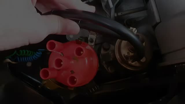 ▶ 13:35 1-4-3-2 firing order, coil, and module
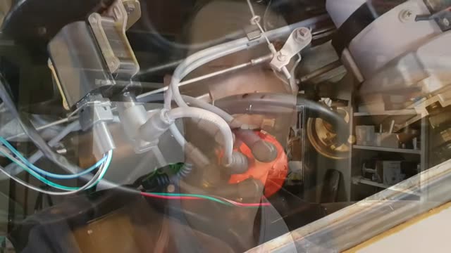 ▶ 20:12 First start & timing adjustment (15° / max. 35°)
Quick Reference Table of Specs, Firing Order, and Timing (VW Brasília 1600)
Scroll horizontally to see all table columns.
| Technical Parameter | Official / Real Specification | Practical Garage Note |
|---|---|---|
| Firing order (Air-cooled VW Boxer) | 1 - 4 - 3 - 2 (clockwise rotor rotation) | Cylinder 1 (front right) · 2 (rear right) · 3 (front left) · 4 (rear left) |
| Initial ignition timing (actual setting) | ~15° BTDC at the first mark (or 10° between marks) | Set at 900 rpm with a timing light; the engine revved cleanly with zero pinging |
| Verified maximum advance | Below 35° total at high rpm | Checked with a timing light to ensure the kit's centrifugal/vacuum advance does not cause detonation |
| Spark plugs used in the setup | NGK B5ES / BP5ES (kept from the car) | Even without resistor plugs, the kit worked flawlessly; new Bosch wires for a pin-type cap |
| Distributor cap type | With pin (electronic ignition standard) | Requires wires with female terminals for the center pin; incompatible with old pinless-cap wires |
| Pin 7 on the electronic module | Pulse signal output (tachometer) | Mentioned in the video for future tachometer installation after validating basic operation |
Tools, Parts, and Supplies Checklist
Scroll horizontally to see all table columns.
| Item / Tool | Specification | Role in Procedure |
|---|---|---|
| Electronic Ignition Kit (Hall Sensor) | Complete distributor + module + harness + pin-type cap + rotor + dust shield | Replaces the entire mechanical points and condenser system (~R$ 135 on Mercado Livre) |
| Spark Plug Wire Set | Bosch for distributor pin-type cap | Secure connection on the new cap pins and the coil tower |
| Stroboscopic Timing Light | With digital/analog advance | Accurate verification of 10° to 15° initial timing and ceiling below 35° total |
| Digital Multimeter | Continuity / 12V voltage scale | Test true grounding between module, body, and battery negative, and identify switched power |
| Combination Wrenches / Sockets | 10 mm, 13 mm, and flathead screwdriver | Loosen distributor clamp, mount coil bracket, and secure module to the body |
| WD-40, Clean Oil, and Permanent Marker | Assembly aid | Lubricate distributor O-ring, ease wire boot seating, and mark 1-4-3-2 on the cap |
Step by step — Start: Kit Inspection, Marking Cylinder 1, and the Shaft Secret
Inspecting the Hall Kit and Cap With Pin vs. Without Pin Difference
Before disconnecting any wire on the Brasília, lay the kit out on the workbench and verify the four essential components: distributor with Hall sensor (complete with dust shield, rotor, and cap), ignition module, plug-and-play harness, and brackets. Immediately compare the new cap against the old one: the original points distributor uses a cap without pin, while the modern electronic kit uses a cap with pin.
Compatibility tip: confirm right away that your spark plug wire set and coil wire have terminals compatible with a pin-type cap (in the video, Paulo used a new Bosch wire set he had saved from an earlier purchase). The car's NGK plugs were kept with no issues.
▶ at 00:05 in the video ↗Aligning the Pulley at the TDC Mark and Identifying Cylinder 1
Pro tip before loosening the old distributor: turn the engine by hand until the crankshaft pulley mark aligns with the crankcase split seam. With everything still assembled, pull the old cap and note which way the rotor is pointing — at that mark, the engine can only be at firing position for cylinder 1 or cylinder 3.
Marking which wire goes to cylinder 1 while the old system is still in place saves hours of trial and error later. Also keep the old distributor hold-down clamp and coil bracket, since the aftermarket kit does not include those metal plates.
▶ at 02:53 in the video ↗The Secret of the Asymmetric Drive Dog and Inverted Rotor in the Aftermarket Kit
On the bench, look at the bottom end of the distributor shaft that engages the drive pinion inside the block: the tang/slot is offset to one side (asymmetric) specifically so the distributor cannot be installed 180° backwards — if forced the wrong way, when the engine spins the rotor pops off and the car stalls.
The critical gotcha shown in the video: even when aligning the asymmetric base of both distributors in the exact same orientation (and even keeping the vacuum canister on the same side), the rotor on the Chinese electronic distributor points in a different direction from the original! If you simply plug the wires into the same physical towers as the old cap, the spark will fire on the wrong cylinder and backfire through the carburetor.
▶ at 07:32 in the video ↗O-Ring Lubrication, Hall Window Alignment, and Seating in the Block
So the new rubber O-ring slides in without tearing at the block bore, coat its exterior with a light film of engine oil. Before dropping the distributor in, slip the hold-down clamp on with the nut still loose so you don't forget it later.
Position the vacuum advance canister at a clear angle (so it won't hit the tinware or carburetor if you need to rotate the housing to advance or retard timing). As a starting reference, align one of the shutter wheel windows directly in front of the Hall sensor, seat the housing all the way down while gently turning the rotor so the drive dog engages, fit the dust shield, and press the rotor onto the shaft's internal slot.
▶ at 10:10 in the video ↗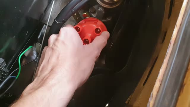
Step by step — Middle: 1-4-3-2 Wires, Coil, Module, and True Grounding
Mapping 1-4-3-2 on the Cap and Installing the Bosch Wires
With the cap seated on the distributor's locating notch, see exactly which cap tower the rotor is pointing toward (with the pulley at the cylinder 1 mark) and write the number 1 on the cap itself with a permanent marker. From there, following the rotor's clockwise rotation, mark 4, 3 and 2.
Spray a tiny bit of WD-40 inside the new wire boots so they slide smoothly all the way down onto the pins without bending the metal terminals, route the wires neatly through the wire looms (Frontec), and mount the coil with its tower angled cleanly toward the bracket.
▶ at 13:35 in the video ↗Mounting the Electronic Module, Plug-and-Play Harness, and Ground Test
To mount the module without drilling unnecessary holes in the body, reuse the threaded mounting holes where the Brasília's old voltage regulator used to sit (using a sturdy metal bracket for heat dissipation and keeping wires from hanging loose near the cooling fan). Secure the harness ground wire and the alternator ground together under the bracket bolt and verify with the multimeter on continuity scale between the bolt and the battery negative post.
The harness wiring is foolproof: the Hall distributor connector will not fit the coil or vice versa. At the coil connector, connect the loose power lead to switched ignition positive (terminal 15). Leave the distributor body just snug (semi-loose) so you can rotate it to find the timing on first start.
▶ at 17:00 in the video ↗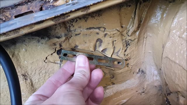
Step by step — End: First Start and Stroboscopic Timing Adjustment
First Start by Turning the Distributor and Warming Up to 900 rpm
Unlike breaker points (which let you set static timing with a test lamp and the engine off), with Hall ignition you crank the engine and gently turn the distributor body back and forth until it catches steadily (in the video, it initially held ~600 rpm while cold).
Next, let the engine warm up and prop the throttle pedal to hold steady around 900 rpm (or have a helper hold it) to take an accurate reading with the timing light.
▶ at 20:12 in the video ↗Final Timing Dial-In (15° Initial and Ceiling Below 35°)
Following the practical reference shared in the video (tip from Sérgio on the Fórum Fusca Brasil): with the timing light set to 15°, align the first pulley mark with the crankcase seam (or ~10° between the two marks). Rev progressively to high rpm while watching total advance on the timing light to make sure it does not exceed 35° — preventing pre-ignition/pinging under load.
Tighten the distributor clamp nut without letting the housing turn, take a road test, and feel the response: with timing dialed in, the air-cooled engine gains low-end torque and revs much more smoothly.
▶ at 24:23 in the video ↗
Post-Installation Verification Checklist
- 1-4-3-2 firing order verified: No crossed wires or loose boots on the pin-type cap.
- Multimeter-tested ground: Solid continuity between the module housing/bracket and the battery negative terminal.
- Distributor locked and harness clear of the fan: Clamp nut tightened after final timing adjustment and wires zip-tied away from the cooling fan intake.
Frequently Asked Questions (FAQ)
Can I install electronic ignition on a Brasília or Beetle without a timing light?
It is possible, but takes much more work. Without a stroboscopic timing light, you have to turn the distributor in small increments, take short test drives, and tune by ear and engine response until it stops misfiring or pinging. A timing light lets you lock in 10°–15° initial timing and verify the 35° ceiling in minutes.
Why did the engine backfire through the carburetor and fail to start after swapping the distributor?
Almost every time, it is because the aftermarket distributor's shaft/rotor came clocked differently from the old unit (offset) and the wires were plugged in by copying the old cap, or a wire was swapped out of the 1-4-3-2order. Find cylinder 1 using the pulley mark + actual position of the new rotor.
Do I need to switch to resistor spark plugs when installing electronic ignition?
In the kit tested in the video (Hall sensor), the conventional NGK plugs already installed in the engine worked normally with zero misfires. What truly requires mandatory attention is matching the spark plug wires to the pin-type cap in the new kit.
Where do I wire the tachometer on this electronic ignition kit?
The electronic module connector has pin 7 dedicated to the rpm signal for a tachometer, in addition to coil negative depending on the gauge model. Verify the car runs perfectly first before tapping the tachometer wire.